|
In April of 2012 the DSP&P Historical Society acquired a circa 1890s automatic link and pin coupler complete with draft gear. Society member Norm Acker spotted the coupler in Waterton Canyon in the Platte River just below today's Strontia Dam. Coordinating with the Denver Water Board it all came together on April 27th, 2012 when Norm, society member Bob Schoppe and Denver water board employees Lance Cloyd and Mark Maring tied a cable around the coupler and with a Denver Water Board truck hauled the up a 50 foot bank to the road, and then loaded it into the back of Norm's truck for the trip to Como. Just a few feet away from the coupler we also found a side cheek plate used to connect the draft gear of this type of coupler to the car frame.
Later, Norm admitted to feeling a bit nostalgic on the way to Como as he thought about these artifacts traveling over Kenosha Pass for the first time in over 100 years!
Ultimately this coupler will be an invaluable element in the restoration of the society's DSP&P RR 1880 Litchfield boxcar no. 608.
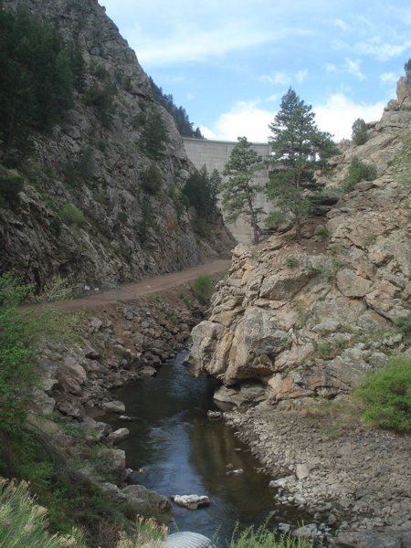 |
1. The location where the coupler has spent the last 100 plus years is to the right of this photo, just a short distance below the Strontia Springs Dam. |
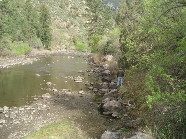 |
2. Looking downstream, with the Strontia Springs Dam behind the photographer, the coupler was in the water just to the left of Norm Acker. |
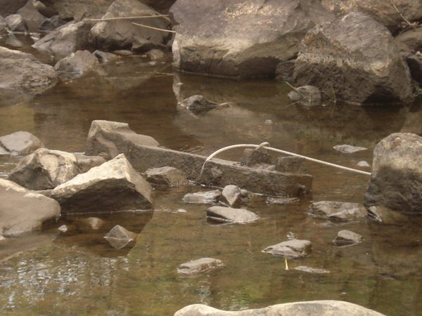 |
3. The coupler with a cable wrapped around it is ready to be hauled up the bank. |
|
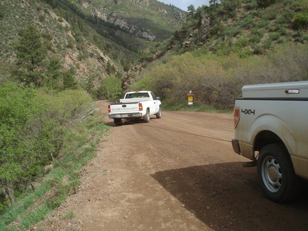
4. Two Denver Water Board trucks, one to provide the proper angle and the other to do the “grunt” work, are hauling the couple up to the road. |
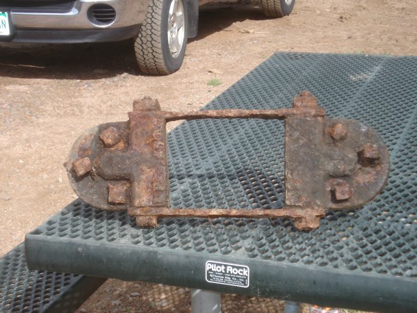 |
5. This cheek plate was found just a few feet from the coupler. |
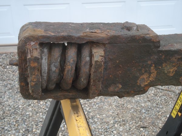 |
6. This view shows the draft gear of an inner and outer spring, and two end plates, which provide the necessary “shock absorbing” capability. |
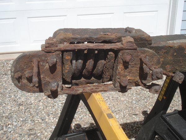 |
7. This view shows how the cheek plate provides the end stops for the spring(s) end plates. The long bolts would have been through a parallel wood beam. (see diagram in image 9) |
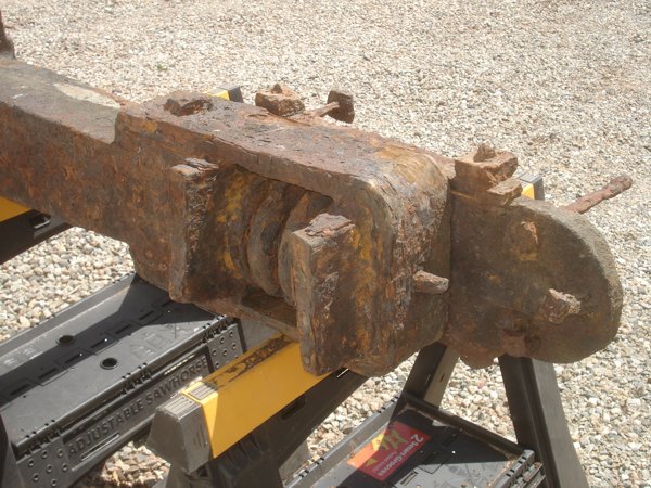 |
8. The reverse view of photo 7. Missing on this side is the other cheek plate. |
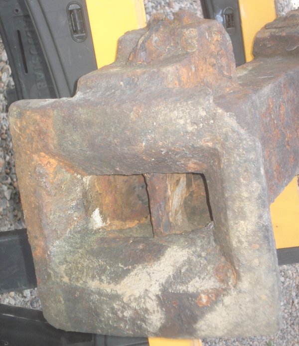 |
8a. The front of the coupler, showing the pin still in place. |
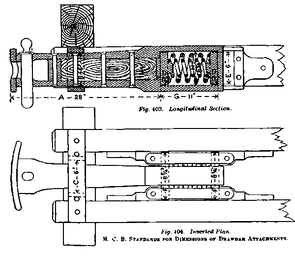 |
9. This schematic appeared in the 1888 Car Builder's Dictionary and clearly demonstrates how this type of coupler was installed. |
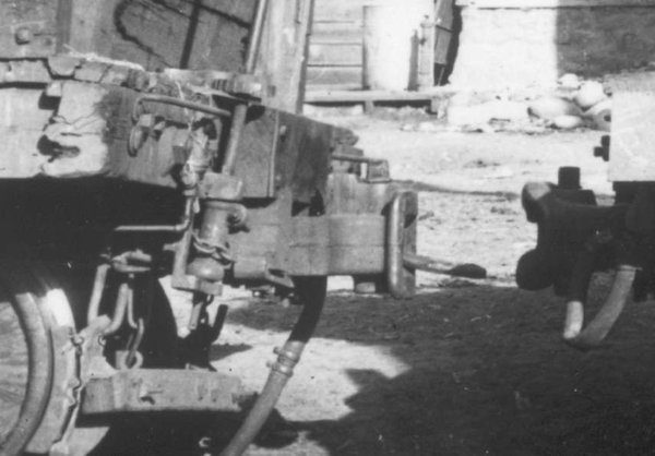 |
10. This view shows an example of this type of coupler installed on a C&S gondola car. The coupler on the right is a conventional link-and-pin coupler, where the pin was removed by hand, and the link needed to be held in position as the cars were brought together. If the brakeman holding the link let go of the link too soon, it could hit the face of the coupler and break. If he held on too long, his hands or fingers could be crushed. The coupler on the left is an automatic link-and-pin like the one we salvaged. The extra piece on top of the coupler works with a special pin to hold the link in the proper alignment as the cars come together. The impact would then cause the pin to drop into the normal position. This was a safety innovation that was used for a short time until the knuckle couplers like those in use today became viable. Todd Hackett collection |
|